What you'll find here...
GENERAL
Your Wastewater Treatment System is a complete, prefabricated system shipped to you ready to be installed at the Owner’s project site. Several of the subassemblies will be shipped loose for field reassembly because shipping limitations will not permit them to be shipped attached to the tank. Before the plant arrives at the job site and you receive shipment, there are some very important details that must be checked by the owner's installing contractor.
Please review the following instructions carefully and study the drawings of your wastewater/sewage plant to obtain a working knowledge of the equipment you will receive. If you should have any questions or need further information, please do not hesitate to contact us immediately at Pollution Control Systems, Inc., telephone 513-831-1165.
These suggestions are for you guidance; by carefully reading them before you begin work, you may avoid costly mistakes. If you should note an error, please contact us immediately. With proper care and by following these suggested and simple instructions, installation time and money can be saved.
Back to Top
SCHEDULED DELIVERY DATE
After production schedules are reviewed, you will be advised of an approximate shipping date. If our schedule does not meet with your site plans, please contact us immediately. If we are not notified before the highway permits have been purchased, the customer will be responsible for any additional cost for new shipping permits if rescheduling is required. The validity of highway permits varies from state to state, usually three to five days.
Back to Top
EXCAVATION
A study of the shop drawings on your System will permit you to determine the size and depth (if any) of excavation needed for your installation. The size of the excavation should be at least two feet wider and longer than the tank dimensions to allow room for anchoring and paint touch-up before backfilling. Pile excavated material far enough away from the excavation to allow trucks and crane to operate safely from either side.
It is desirable to backfill up to a point above the water level in the plant on all four sides to prevent freezing in climates where this condition can occur.
Back to Top
FOUNDATION PAD
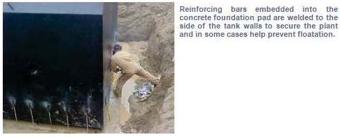
.jpg) Due to the construction of the wastewater treatment system, a concrete foundation slab is necessary. This slab is to be used as a tank base and in some cases for anchoring the vessel to prevent floatation.
Due to the construction of the wastewater treatment system, a concrete foundation slab is necessary. This slab is to be used as a tank base and in some cases for anchoring the vessel to prevent floatation.
The design and construction of this slab is the responsibility of the customer’s Project Engineer. For minimal sizing (slab is being used for alignment purposes only), refer to the foundation slab drawing(s) supplied. These slabs have been sized to accommodate the tank only and are not designed for soil conditions.
To help determine the exact slab design needed, assume that the total weight of the plant will act as a uniformly distributed load acting along the entire length of the foundation slab. If one or more zones in the tank will be empty while others are full, this must be taken into account.
 It is extremely important that the foundation slab is level; if it is not, the system will not function properly. The slab must be level within the following tolerances: 0.5" in 10' across the width and within 0.25" in 10' along the length. Where crowns in the slab, or any other non-standard workmanship exists, they must be corrected by resurfacing the slab, or by placing a sand cushion on top of the slab to achieve full uniform bearing.
The Project Engineer should check the foundation slab before the treatment system arrives. Where floatation conditions exist, as in fluid soil, a foundation slab of adequate size and weight should be supplied to equal the bearing soil pressures. Sufficient anchor bolts and/or rods should be provided to securely anchor the tank to the foundation pad.
Back to Top
SHIPPING
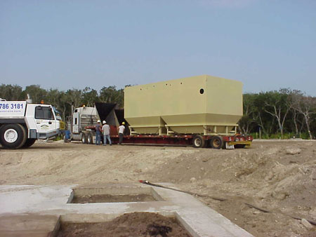 In almost every case, shipment of your prefabricated plant is by special lowboy trucks. Adequate level road access must be provided for the lowboy trucks to access the offloading area of the plant. When your plant is shipped by truck, the delivery will be from the fabrication facilities directly to the job site. When the truck arrives, direct the driver to position the trailer, if possible, so that the hopper end of the tank will be placed at the discharge end of the pad. This will eliminate having to reposition the tanks later.
Back to Top
ALTERNATE MEANS OF SHIPPING
Common carrier service can be used for shipping those systems small enough in both size and weight. In these cases, the plant shall be delivered to the nearest truck dock. It will be the customer's responsibility to arrange moving the system to the project site.
Back to Top
UNLOADING
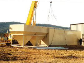
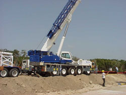 When the plant arrives at the jobsite, the contractor should have the necessary equipment available to unload and set the vessel(s) on the foundation pad. A crane of adequate size is usually the simplest method for unloading the plant. Lifting lugs are supplied on the vessel to ease handling.
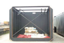
Prior to setting the tank(s) in position, check the inside of all chambers for pallets, boxes, bags, and loose pieces of equipment that have been placed there for shipping. Remove these pallets with the crane before it leaves the project site and prior to setting the tanks in position on the foundation pad.
The blower/motor unit(s), control panel(s), handrail(s), and magnesium anodes are typical of these items. After setting the plant in position, check to be sure that it is level and in correct position.
 Our package wastewater treatment system will be completely assembled and shipped as a unit where shipping dimensional regulations permits this procedure. If a portion of the equipment is packaged separately at the factory for field assembly, the equipment will need to be installed by the contractor in the field.
 The blower/motor unit(s) should be lifted onto the plant from inside the tank by a crane. Each housing mounts on structural members drilled to receive the vibration dampeners that mount between the housing and the structural member. Be sure to align the blower discharge piping (which extends from the bottom of the housing) with the plant air supply line (which is stubbed up from the plant air manifold). The connection between the blower discharge piping and the air manifold stub pipe is by use of a rubber hose and hose clamps. Please refer to the typical blower/motor mounting detail drawing in the O&M manual supplied.
Back to Top
ELECTRICAL CHARACTERISTICS
Special precaution should be taken to make sure the correct electrical requirements are supplied at the job site. Check your data sheet and wiring diagrams, then advise your electrical contractor as well as the local Power Company of the necessary power requirements.
A disconnect switch mounted within sight (adjacent to the plant site) and wiring from this switch to the control panel on the plant, must be furnished and installed in accordance with the local Electrical Codes. The contractor also must connect the wire leads provided to hook up the blower/motor units, spray pumps, equalization pumps, floats, and/or any other accessories provided with the plant to their proper terminals in the control panel.
It is important that proper blower/motor rotation be maintained. Improper rotation will cause damage to the blower by allowing water to be pumped back from the plant rather than air being pumped to the plant. Failure to check proper rotation will result in voiding the blower warranty.
Electrical Hook Up: The electrical contractor must provide final field hook up. A wiring diagram showing details of this hook up will be found inside the door of the control panel.
Back to Top
MISCELLANEOUS ITEMS
The following items are a few final details that should be checked out by the owner or the owner's contractor BEFORE the plant arrives.
Site Check: The excavation and foundation pad should be checked to see that it is clear of all mud, water, or debris: that the excavation is clear of dirt piles around the adjacent area for truck and crane operation.
Unloading Facilities:
- Arrangements should be made for obtaining a crane with sufficient capacity to lift and boom the tank over and onto the base pad.
- The steel tank(s) will have lifting lugs for use with four-leg cable slings or with spreader bars to prevent undue stress on the lifting lugs.
- If a crane is not available, be sure that other means of unloading are fully prepared and ready. If the tank is to be dragged or slid off the truck, the contractor will be responsible for any and all damage to the lowboy trailer and/or to the tank and its components. PLEASE NOTE: PCS does not recommend this method of tank removal.
Sewage Connections: All sewage connections to and from the plant are the responsibility of the owner/contractor.
Back to Top
WARNING
Before leaving the project site once the system has been set and anchored into position, all drain plugs must be installed and all tanks filled with water. These tank structures are very buoyant and can float easily when installed below grade. Be sure that all equipment shipped loose inside the tank is removed.